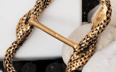
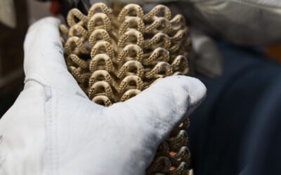
A design studio sends its supplier a PDF with three views, two dimensions and a note: “brushed gold finish”. Two days later a reply arrives, and it is not a quotation. It is a list of questions. How many pieces. Which alloy. Which dimensions are binding and which are indicative. Is the logo engraved or raised, and by how much. What is the thinnest wall on the part.
This exchange happens thousands of times a year across the industry, and every time it costs a week. The reason is that a technical drawing for fashion hardware, however carefully prepared, describes a shape and nothing else. Everything that turns that shape into a manufacturable object sits outside the geometry. Below is what is missing, and why.
Why your supplier asks for the 3D file rather than the dimensioned drawing
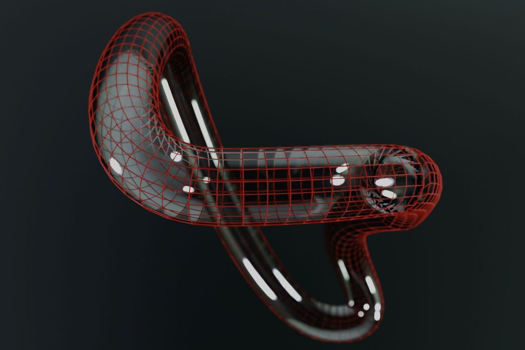
A metal accessory almost always has doubly curved surfaces, variable fillets, raised details and undercuts. A two dimensional drawing cannot describe those shapes unambiguously: two engineers reading the same dimensioned view can reconstruct two different parts, and both of them comply with the drawing. The 3D model, by contrast, is the geometry. From it the casting pattern, the toolpath or the print file are derived directly, with no interpretive step in between. The dimensioned drawing does not disappear, but its role changes: it no longer describes the shape, it declares which dimensions are critical and to what tolerance.
Which file format to send
The difference between formats is not an IT detail. It changes what your supplier actually receives.
- STEP: a neutral format that preserves exact geometry, with surfaces described mathematically. This is the exchange format to prefer, because any software opens it without loss of precision.
- STL: describes the surface as a mesh of triangles. It is an approximation by construction, so a circle becomes a polygon. Perfectly fine for a 3D printed check, much less so as a production reference, because the accuracy depends entirely on how the export was configured.
- Native format (Rhino, SolidWorks, Fusion and similar): useful when your supplier runs the same software, since it preserves the feature history and makes revisions far quicker.
The most effective approach is to send all three: the native file, a STEP as a guarantee that it will open, and a reference PDF carrying the critical dimensions and notes. It takes two minutes and removes an entire round of emails.
The most effective approach is to send all three: the native file, a STEP as a guarantee that it will open, and a reference PDF carrying the critical dimensions and notes. It takes two minutes and removes an entire round of emails.
Files in .stl format usually represent a shape more organic and less geometric than other formats, a thing that is usually impossible to realize on CAD programs like Rhinoceros or Visicad. Zbrush, Blender and Sculptris are instead programs that use .stl extension.
The six things geometry does not tell you
Even the most carefully built 3D model describes a shape and nothing more. Everything else has to be stated separately, and usually is not.
1. The material
Not “metal”, and not even “brass”: the alloy. Brass, bronze, zamak and aluminium behave differently in casting, weigh differently for the same volume, and respond differently to finishing. A part designed for zamak and produced in brass feels noticeably different in the hand, and on fashion hardware perceived weight is part of perceived value.
2. The finish, and its thickness
A finish is not paint applied over a shape that is already complete. It changes the geometry. Electroplating adds material, in small but not negligible amounts, while tumbling and satin finishing remove it and soften edges.
The consequences are concrete. A fit designed with zero clearance seizes after plating. A shallow engraving fills in and disappears. A sharp edge that defines the character of the part in the rendering comes out of the tumbling barrel rounded off. Whoever designs the part needs to know which finish is coming, because the shape has to be drawn for that finish, not for bare metal.
3. Which dimensions are critical
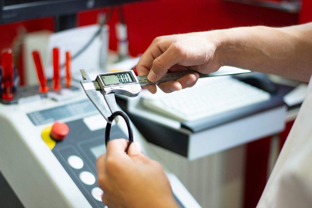
On a drawing every dimension looks the same, but they do not carry the same weight. On a belt buckle the internal strap width is binding: half a millimetre out and the strap either will not pass or rattles. The thickness of the frame, on the other hand, can vary without anyone noticing.
Calling out two or three critical dimensions with their tolerances, and leaving the rest indicative, is more useful than dimensioning everything to the same precision. Tightening every tolerance drives up the price through inspection that serves no purpose, and occasionally makes the part impossible to produce at a sensible cost.
4. The quantity, and the one after it
The same part is made in different ways depending on the numbers, and the choice of process changes what can be designed. But the quantity that matters is not only the first order. Knowing that a reorder of ten thousand pieces is expected after the sampling stage changes whether it makes sense to tool up straight away or wait. This is the piece of information design studios omit most often, because they treat it as commercial rather than technical.
5. Acceptance criteria
What counts as a defect and what is simply a characteristic of the process. Micro porosity on an internal surface that is never seen is normal in casting; the same porosity on the face of a logo plate is not. A slight difference in tone between two plating batches falls within normal process variation, beyond a certain threshold it does not.
If these criteria are not agreed beforehand, they will be argued about afterwards, with the parts already made and a delivery date to meet. That is the situation in which neither side is right, because nothing was ever written down.
6. The real end use
Where the part sits on the finished product, how hard it is worked, and whether it touches the wearer’s skin. A component intended for direct and prolonged skin contact falls under the European restriction on nickel release, and that conditions the choice of plating cycle. None of it can be inferred from the geometry. It has to be stated.
The mistakes that keep coming back
Some recur with striking regularity, and nearly all of them come from a model built to be looked at rather than to be made.
- Walls that are too thin. Below a certain threshold the metal will not fill the cavity, or the part distorts. That threshold depends on the alloy, the process and how far the wall extends, so it is a question to put to your supplier before modelling, not after.
- Very uneven wall thickness within one part. Thick sections solidify more slowly than thin ones and shrink more, which produces distortion and internal voids. Evening out thicknesses, or hollowing heavy masses, solves the problem at the design stage.
- Sharp edges everywhere. A fillet, even a minimal one, helps the metal fill, reduces stress concentration and survives finishing. The perfectly sharp edges in the model will not exist on the real part under any circumstances, so it is better to decide where to soften them than to let the process decide.
- Undercuts that cannot be released. Some are manageable, others force expensive workarounds or make the part unproducible by that process. Worth checking before the model goes in front of the end client.
- Logos and engravings that are too fine. A relief of a few tenths is lost in casting or drowned by the finish. Lettering has to be sized for what will survive plating and tumbling, not for how it looks in the rendering.
- A model drawn at final size. Metal shrinks as it solidifies, and finishing adds or removes material. Your supplier compensates for this, but needs to know that the dimensions in the file are the ones wanted on the finished part rather than figures to reproduce literally. That too should be written down.
- Open geometry. Unclosed surfaces, overlapping faces, solids that are not watertight. The file opens, it looks fine, and it is not manufacturable. It has to be rebuilt.
The list to attach to your file
Seven lines which, sent alongside the model, remove almost all of the back and forth that follows:
- The alloy required.
- The finish required, with a visual reference where one exists.
- The two or three critical dimensions, with tolerances.
- First order quantity and expected reorder volume.
- End use: which product, which position on it, skin contact or not.
- Acceptance criteria, at least for visible surfaces.
- The date the sample is needed and the date production is needed, stated separately.
The point
A 3D file is not a production order. It is a description of a shape. Everything that makes that shape a real object sits outside the geometry and has to be said explicitly. What it is made of, how it is finished, how precise it has to be, how many are wanted, and what makes it acceptable.
Studios that do this cut weeks off the development phase and reach the first sample with far fewer surprises. Studios that do not are not saving time. They are moving it further down the line, to the point where it costs more. The most effective way to avoid the exchange altogether is to involve whoever will make the part while the model is still being built, when changing a wall thickness or a fillet is a matter of minutes. Micromet works with design studios and product teams at exactly this stage, before the drawing is closed: see how our 3D design of metal components service works.